Ike Alisson The below attached information related to 5G Security is previosly sent to ONAP Enterprise Task Force. It is dated Augusti 2021. The title was : Remarks on the Security aspect in 5GS and LTE/EPC E-UTRA related to Magma".
Upon any interest, the attached below content can be updated in line with the latest published 3GPP specifications related to the respective aspect to 5G.
- Input on Security Architecture in 5G (SA & NR)
2. Input on the difference between EPC/LTE (Magma) and 5G SA NR related to RRC Inactive state evolvement as an enhancement to Vertical/Enterprise Solutions UCs (SST categories eMBB, URLLC, MIoT, V2X, HMTC, URLLC and PNI-NPN (S-NEST & P-NEST).
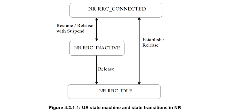
With regard to point 2 above, please note that in both, EPC/LTE/Magma and 5G SA NR enhancement, the RRC Inactive "integrity" message is preserved, as also in the 5G SA NR RRC Inactive state (it is the same, no difference).
Nevertheless, in 5G SA NR RRC Inactive state, there is added an evolvement related to enhanced "Security" in terms of Encryption of the sent message to the UE for "Release/Suspend" from "Connected" State to "Inactive" State (within the defined RNA and "hidden" from the CN). The same "encrypted" message is used to generate Security Key when there is sent a request encrypted message for the UE to "resume/connect" and change state (due to the need to transmit Data/message) from "Inactive" to "Connected" state and the previously sent Encrypted message to the UE, is used to generate a Security Key to change state from "Inactive" state to "Connected" state. (P.S. This encrypted message is also used to generate Security Keys for other purposes/functions related to UE's move within the RNA or out of the RNA as well...)
In addition to the added/enhanced Security in 5G SA NR, dislike LTE/EPC/ (Magma), there is also a substantial reduction in number of Signalling (from 7 to 3 messages) in the "new" RRC Inactive state enhancement....please see attached further below).
These addedd enhancements in 5G SA NR, dislike LTE/EPC/Magma, do not only contribute to meet the Latency QoS/5QI for defined UCs Services, but also substantially contribute to Battery saving Power Consumption (PSM, DRX, TAU) as well as Location Management Function and Paging within a defined UEs RNA.
I do not add any info about NAS, CM, RM, RNTI, I-RNTI, RAN based Location Management, RNA Paging, that is also very relevant to the specified UCs Enterprise Services defined QoS/5QI requirements.
The above might definitely be inquired when you try to offer LFN 5G Super Blueprint Solution in your endeavour for setting up PNI-NPN (S-NEST/P-NEST) SST for offerring to the Verticals as NSaaS. ....Nothing personal, but if I am sitting "across the table..."on the opposite side" of you... and not like now "sitting next to you"....I will definetely ask you series of Questions related to the 5GS Network and Exposure Capabilities and their impact on the specified Services.... The main challenge is that "Now the Information is Open/Accessible by everyone and accessible 7/24h"...so it is not any longer about "presenting the info", but making connection to the points that seemingly are not related, identifying current and latent/potential problems, but about future inter-dependencies....since the info is ubiquitous...
While at the moment several MNOs are in process of deploying 3GPP Rel 16, in case of offering PNI-NPN as NSaaS Solution to selected Verticals/Enterprises, you may get a question/inquiry about why offering/proposing an "older" version/Solution to them, that lacks selected Features/Capabilities, instead of the latest/recent Functionalities and Capabilities that, not only can contribute to improve their CAPEX & OPEX for the new Services, but also through that make them more Competitive and attractive in the Market...
- Input on 5G SBA Security Architecture:
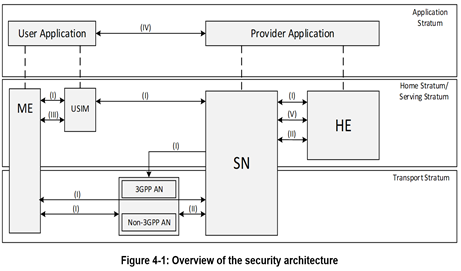
The figure illustrates the following Security Domains:
- Network Access Security (I): the set of security features that enable a UE to authenticate and access services via the network securely, including the 3GPP access and Non-3GPP access, and in particularly, to protect against attacks on the (radio) interfaces. In addition, it includes the security context delivery from SN to AN for the access security.
- Network Domain Security (II): the set of security features that enable network nodes to securely exchange signalling data and user plane data.
- User Domain Security (III): the set of security features that secure the user access to mobile equipment.
- Application Domain Security (IV): the set of security features that enable applications in the user domain and in the provider domain to exchange messages securely. Application domain security is out of scope of the present document.
- SBA Domain Security (V): the set of security features that enables network functions of the SBA architecture to securely communicate within the serving network domain and with other network domains . Such features include network function registration, discovery, and authorization security aspects, as well as the protection for the service-based interfaces. SBA domain security is a new security feature.
- Visibility and Configurability of Security (VI): the set of features that enable the user to be informed whether a security feature is in operation or not.
NOTE: The visibility and configurability of security is not shown in the figure.
4.2 Security at the perimeter of the 5G CN (Core Network)
4.2.1 Security Edge Protection Proxy (SEPP)
The 5G System Architecture introduces a Security Edge Protection Proxy (SEPP) as an entity sitting at the perimeter of the PLMN for protecting Control Plane (CP) messages.
The SEPP enforces inter-PLMN Security on the N32 interface.
4.2.2 Inter-PLMN UP Security (IPUPS)
The 5G System Architecture introduces Inter-PLMN UP Security (IPUPS) at the perimeter of the PLMN for protecting User Plane (UP) messages.
The IPUPS is a functionality of the UPF that enforces GTP-U Security on the N9 Interface between UPFs of the Visited and Home PLMNs.
NOTE: IPUPS can be activated with other functionality in a UPF or activated in a UPF that is dedicated to be used for IPUPS functionality (see also 3GPP 5G System Architecture specification related to IPUPS clause.
4.3 Security entities in the 5G CN (Core Network)
The 5G System Architecture introduces the following Security Entities in the 5G Core Network:
AUSF: AUthentication Server Function;
ARPF: Authentication credential Repository and Processing Function;
SIDF: Subscription Identifier De-concealing Function;
SEAF: SEcurity Anchor Function.
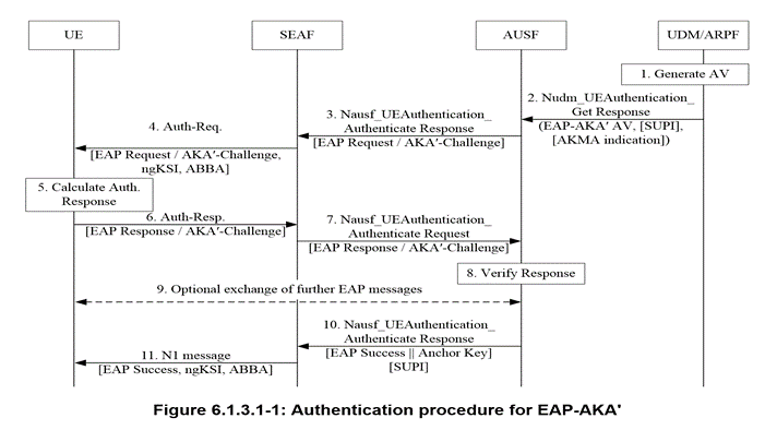
6.1.3 Authentication procedures
6.1.3.1 Authentication procedure for EAP-AKA'
EAP-AKA' is specified in RFC 5448. The 3GPP 5G profile for EAP-AKA' is specified in the normative Annex F.
The selection of using EAP-AKA' is described in sub-clause 6.1.2 of the present document.
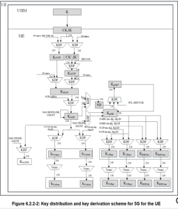
6.2 Key Hierarchy, Key Derivation, and Distribution Scheme
6.2.1 Key Hierarchy
Requirements on 5GC and NG-RAN related to keys are described in clause 5.1.3. The following describes the keys of the key hierarchy generation in a 5GS in detail.:
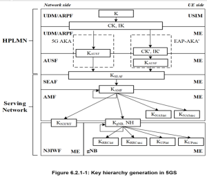
Keys for RRC signalling:
- KRRCint is a key derived by ME and gNB from KgNB, which shall only be used for the protection of RRC signalling with a particular integrity algorithm.
- KRRCenc is a key derived by ME and gNB from KgNB, which shall only be used for the protection of RRC signalling with a particular encryption algorithm.
Keys in the N3IWF
The N3IWF receives KN3IWF from the AMF.
The N3IWF shall use KN3IWF as the key MSK for IKEv2 between UE and N3IWF in the procedures for untrusted non-3GPP access, cf. clause 11.
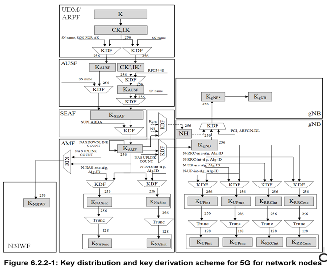
Figure 6.2.2-1 shows the dependencies between the different keys, and how they are derived from the network nodes point of view.
NOTE 4: The key derivation and distribution scheme for standalone non-public networks, when an authentication method other than 5G AKA or EAP-AKA' is used, is given in Annex I.2.3.
6.2.2.2 Keys in the UE
For every key in a network entity, there is a corresponding key in the UE.
Figure 6.2.2-2 shows the corresponding relations and derivations as performed in the UE.
- Input on RRC Inactive state in E-UTRA/EPC/LTE and 5G SA NR
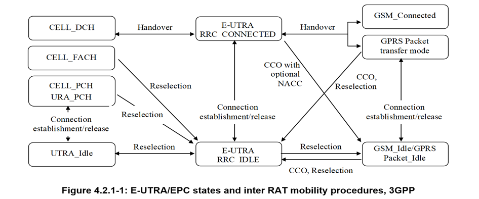
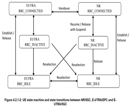
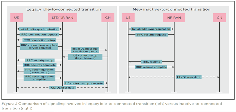
As illustrated on the right side of Figure 2 , the resume procedure reduces the number of RRC messages exchanged over the radio interface between the UE and the RAN to three (down from seven for idle state). RRC resume also has the possibility of using efficient delta signaling – in which only changed parameters are signaled – to restore the configuration of a UE in the inactive state. This option is not possible for UEs in the idle state.
Algorithms for Ciphering and Integrity Protection
1 Null Ciphering and Integrity Protection Algorithms
The NEA0 algorithm shall be implemented such that it generates a KEYSTREAM of all zeroes (see sub-clause D.2.1). The length of the KEYSTREAM generated shall be equal to the LENGTH input parameter. The generated KEYSTREAM requires no other input parameters but the LENGTH. Apart from this, all processing performed in association with ciphering shall be exactly the same as with any of the ciphering algorithms specified in this Annex.
The NIA0 algorithm shall be implemented in such way that it shall generate a 32 bit MAC-I/NAS-MAC and XMAC-I/XNAS-MAC of all zeroes (see sub-clause D.3.1). Replay protection shall not be activated when NIA0 is activated. All processing performed in association with integrity (except for replay protection) shall be exactly the same as with any of the integrity algorithms specified in this annex except that the receiver does not check the received MAC.
NOTE 1: The reason for mentioning the replay protection here is that replay protection is associated with integrity.
The NIA0 shall not be used for signalling radio bearers (SRBs) except for unauthenticated emergency sessions for unauthenticated UEs in LSM.
The NIA0 shall not be used for data radio bearers (DRBs).
NOTE 2: A UE with a 2G SIM is considered to be in LSM in NR.
NOTE 3: NEA0 and NIA0 provide no security.
2 Ciphering Algorithms
2.1 128-bit Ciphering Algorithms
2.1.1 Inputs and outputs
The input parameters to the ciphering algorithm are a 128-bit cipher key named KEY, a 32-bit COUNT, a 5-bit bearer identity BEARER, the 1-bit direction of the transmission i.e. DIRECTION, and the length of the keystream required i.e. LENGTH. The DIRECTION bit shall be 0 for uplink and 1 for downlink.
Figure 2.1.1-1 illustrates the use of the ciphering algorithm NEA to encrypt plaintext by applying a keystream using a bit per bit binary addition of the plaintext and the keystream. The plaintext may be recovered by generating the same keystream using the same input parameters and applying a bit per bit binary addition with the ciphertext.
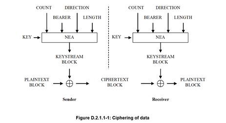
Based on the input parameters the algorithm generates the output keystream block KEYSTREAM which is used to encrypt the input plaintext block PLAINTEXT to produce the output ciphertext block CIPHERTEXT.
The input parameter LENGTH shall affect only the length of the KEYSTREAM BLOCK, not the actual bits in it.
2.1.2 128-NEA1
128-NEA1 is identical to 128-EEA1 as specified in Annex B of TS 33.401 [10].
2.1.3 128-NEA2
128-NEA2 is identical to 128-EEA2 as specified in Annex B of TS 33.401 [10].
2.1.4 128-NEA3
128-NEA3 is identical to 128-EEA3
3 Integrity algorithms
3.1 128-Bit integrity algorithms
3.1.1 Inputs and outputs
The input parameters to the integrity algorithm are a 128-bit integrity key named KEY, a 32-bit COUNT, a 5-bit bearer identity called BEARER, the 1-bit direction of the transmission i.e. DIRECTION, and the message itself i.e. MESSAGE. The DIRECTION bit shall be 0 for uplink and 1 for downlink. The bit length of the MESSAGE is LENGTH.
Figure 3.1.1-1 illustrates the use of the integrity algorithm NIA to authenticate the integrity of messages.
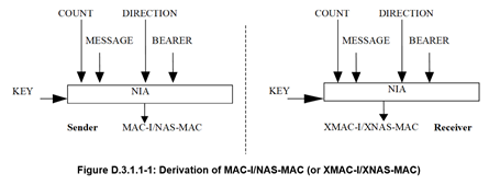
Based on these input parameters the sender computes a 32-bit message authentication code (MAC-I/NAS-MAC) using the integrity algorithm NIA. The message authentication code is then appended to the message when sent. For integrity protection algorithms, the receiver computes the expected message authentication code (XMAC-I/XNAS-MAC) on the message received in the same way as the sender computed its message authentication code on the message sent and verifies the data integrity of the message by comparing it to the received message authentication code, i.e. MAC-I/NAS-MAC.
3.1.2 128-NIA1
128-NIA1 is identical to 128-EIA1 as specified in Annex B of TS 33.401 [10].
3.1.3 128-NIA2
128-NIA2 is identical to 128-EIA2 as specified in Annex B of TS 33.401 [10].
3.1.4 128-NIA3
128-NIA3 is identical to 128-EIA3
4 Test Data for the security algorithms
4.1 General
Annex contains references to the test data for each of the specified algorithms.
4.2 128-NEA1
For 128-NEA1 is the test data for UEA2 in TS 35.217 [36] can be reused directly as there is an exact, one-to-one mapping between UEA2 inputs and 128-NEA1 inputs.
4.3 128-NIA1
For 128-NIA1 is the test data for 128-EIA1 can be reused directly as there is an exact, one-to-one mapping between 128-EIA1 inputs and 128-NIA1 inputs.
4.4 128-NEA2
For 128-NEA2 is the test data for 128-EEA2 in clause C.1 of TS 33.401 [10] can be reused directly as there is an exact, one-to-one mapping between 128-EEA2 inputs and 128-NEA2 inputs.
Sincerely yours,
Ike
_____________________________
This communication is confidential and intended solely for the addressee(s). Any unauthorized review; use, disclosure, or distribution is prohibited. If you believe this message has been sent to you in error, please notify the sender by replying to this transmission and delete the message without disclosing it. Thank you. E-mail including attachments is susceptible to data corruption, interruption, unauthorized amendment, tampering and viruses, and we only send and receive e-mails on the basis that we are not liable for any such corruption, interception, amendment, tampering or viruses or any consequences thereof.
Från: Cxxxxxx.Lxxxxx
Date: tors 5 aug. 2021 kl 16:02
Subject: [onap-enterprise] ONAP for Enterprise Business Task Force - MoM/Action Items (August 4th, 2021) and Agenda (August 18th, 2021)
To: onap-enterprise@lists.onap.org <onap-enterprise@lists.onap.org>
Dear ONAP Enterprise Task Force,
Thank you to the ones who could attend our latest sessions on August 4th, 2021.
Thank you to Dr Erik Kline who introduced SABRES (Secure, Adaptive, roBust, Resilient, and Efficient Slices) – a proposal to “Secure” Network Slice.
Thank you to Gervais-Martial Ngueko for sharing his initial thoughts about ONAP/SABRES integration
The next meeting will be scheduled on August 18th, 2021 at 7.30am PST.
If you want to share any particular topic and/or progress then feel free to update the upcoming sessions/wiki.
Wiki Link: https://wiki.onap.org/display/DW/TSC+Task+Force%3A+ONAP+for+Enterprise+Business
Feel to update/remove/add anything
Please find few notes from the meeting, recording has been posted
Next Agenda
#1 Follow-up on Michael August's questions - In order to document a test plan about how to evaluate the network slicing security research being done by Dr. Kline's team. Can the ONAP Community provide information about:
1) Is there an API within ONAP's VNF Manager component or Element Management that enables assignment/allocation to specific pieces of hardware within the NFVI/cloud infrastructure?
2) If the underlying VIM provides APIs for placement of virtual resources on specific pieces of physical hardware, then does ONAP provide corresponding APIs that the VNFs can use to leverage these VIM placement APIs to perform precise placements of the virtual resources they use onto specific nodes within the physical infrastructure? It also depends on what the VNF/CNF/PNF provide as information.
3) Are there APIs between the Network Slice Instance layer and the Resource layer (resource management functions) that enable a network slice instance to gain information about the current mapping of network slice instances to physical resources? Likewise, are there APIs that enable the network slice instances to leverage specific resources available within the resource layer
#2 ONAP Service Assurance based on Magma Glacier Peak v1.6
#3 Magma/ONAP Integration - latest updates
Remaining Action Items
Best regards
C